Analog Signal Units
The Analog signal units allow for either a current or voltage analog output from the sensor.
The different models are:
| Depth Rating | Function | |
|---|---|---|
| DTU-A | Non-Submersible | DTU and Analog out functions - Current or Voltage out |
| ACU300 | 300m | Analog out functions - Current out |
| ACU1250 | 1250m | Analog out functions - Current out |
| AVU300 | 300m | Analog out functions - Voltage out |
| AVU1250 | 1250m | Analog out functions - Voltage out |
- The units can be terminated via SubConn or pigtail
- The units require power (6 - 40 V) and connection to the analog input of the telemetry unit
- The units have RS232 comms which can be used to validate and upgrade the firmware
Range
| Spec | Range | Notes |
|---|---|---|
| pH | 2 - 10 pH | |
| Current Output | 4 - 20 mA | 20 mA = no available value 4 - 19 mA = proportional to pH value |
| Voltage Output | 0 - 5 V | > 4.9 V = no available value 0 - 4.9 V = proportional to pH value |
⚠️ Note: The analog units require a 12 V / 250 mA power supply
DTU-A
| DTU-A |
|---|
| Picture coming soon! |
The DTU-A communicates to the sensor through the RS485 wires.
⚠️ Tip: We recommend a splice kit when connecting the DTU-A to a pigtailed sensor.
- Make sure the sensor is in autonomous mode
- Connect the DTU-A to the sensor and telemetry unit using the wiring instructions below
- Turn on the power and the sensor will beep
- Wait for first measurement output (until the sensor provides a measurement there is no change on the output)
| 6 Pin DIN | Colour | Connect to | Notes | Current Sensing Equipment | Description |
|---|---|---|---|---|---|
| 1 | Green/White | Loop Current Supply +V | 4-20mA Loop Input 24V Max | ||
| 2 | Orange | DVM +V | 0V to 5V output | ||
| 3 | Black | Sensor Supply 0V | Sensor Power 0V | ||
| 4 | Green | Current sensing equipment input | Through a 250 ohm resistor if required | Connect Current Output to -Loop Current 0V (dual supply) -Sensor Supply 0V (single supply) | 4-20 mA Loop Output |
| 5 | Red | Sensor Supply +V | Sensor Power 24V Max | ||
| 6 | Orange/White | DVM 0V | 5V Ground Reference |
ACU/AVU
| ACU/AVU300 and ACU/AVU1250 |
|---|
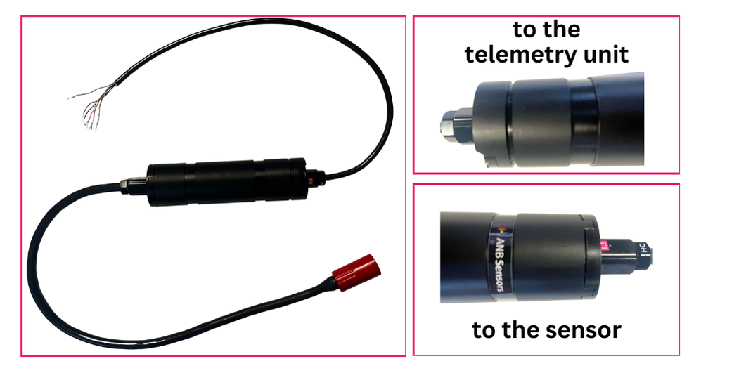 |
- Make sure the sensor is in autonomous mode
- If you have a SubConn terminated unit, connect the sensor to the SubConn end
If you have a pigtailed terminated unit, connect the sensor using these wiring instructions
caution
Ensure you have the unit connected the correct way round, as per the picture above
- Connect the unit to the telemetry unit using the wiring instructions below
- Turn on the power and the sensor will beep
- Wait for first measurement output (until the sensor provides a measurement there is no change on the output)
| Pin | Function to Telemetry Unit |
|---|---|
| Black | Ground |
| Red | Power |
| Green/White | RS232 Sensor Receive |
| Green | RS232 Sensor Transmit |
| Orange | Vout 0-5V / Current Loop |
| Orange/White | Vout 0V / Current Loop |
For further support please contact support@anbsensors.com